Cable Accessory
Achieve best performance results with our range of low loss cable accessories at attractive prices.
We also customize cables to your specific requirements for length and connectors on request.
If you want to learn more about loss and find out how much is acceptable for your application, see below
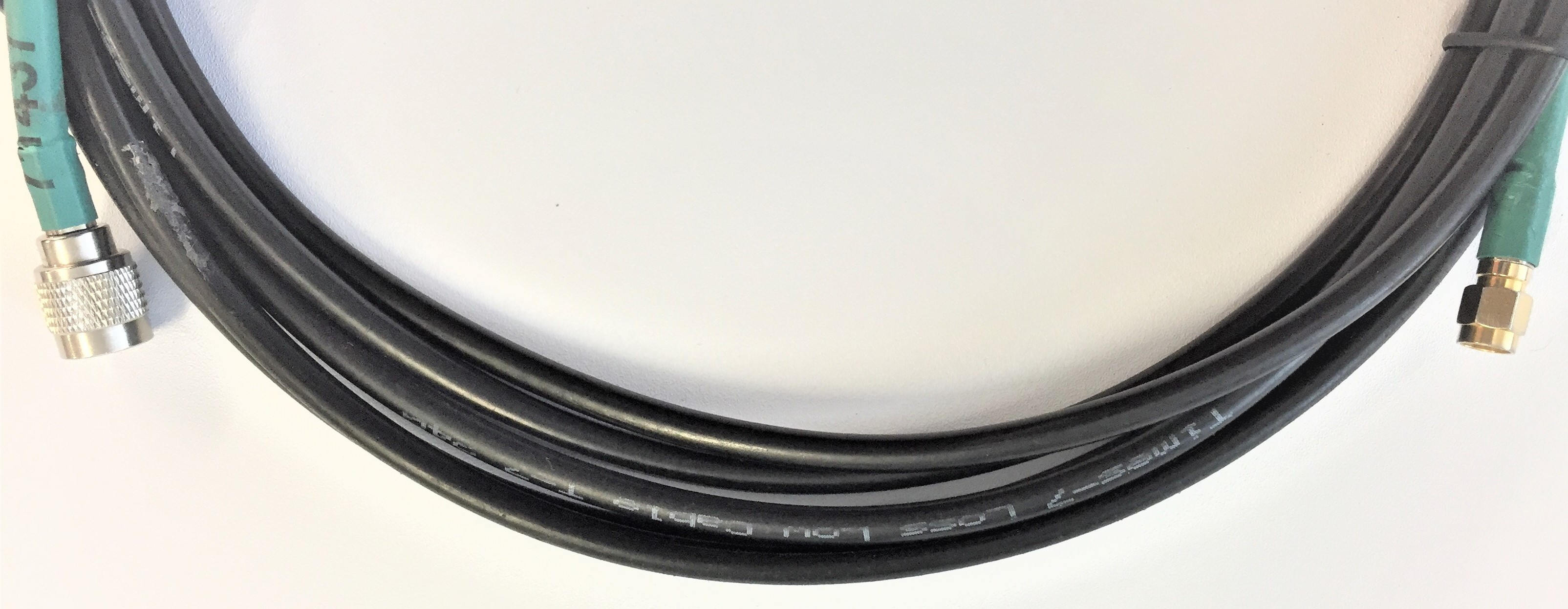
T-7 Cables: Low Loss - Low Cost
Times-7 manufactures connectorized antennas as shown in the picture below. Consequently, you need an extension lead to connect our antennas to a reader.
Just like with every other component of your RFID application, the better the quality of the selected cable the better the performance. That’s why we offer a range of high-quality, low loss cables at attractive prices.
Why low loss?
The losses influence the read range of your antenna.
The following rule-of-thumb applies:
The longer the coaxial cable, the more power is lost between the reader and the antenna, therefore a shorter read distance is the outcome.
It is recommended to deploy the antenna as close to the reader as possible. If the application does not allow for short cables, make sure you select a low loss cable.
Because low loss is key
All coaxial cables involve cable losses to a certain degree, including Times-7’s low loss cables. The table below shows the loss for our standard cable lengths in the UHF RFID frequency (865-928MHz):
Cable Type | Cable Length | Approx. Losses (dB) |
T-7 195 | 2 m | 0.65 |
4 m | 1.30 | |
6 m | 1.95 | |
8 m | 2.60 | |
T-7 240 | 2 m | 0.39 |
4 m | 0.78 | |
6 m | 1.17 | |
8 m | 1.56 |
Tip: Test how much loss is acceptable for your application before you buy a cable.
You can test how much power loss is acceptable for your application before buying a cable by reducing the power of your reader to simulate the loss.
We will explain how:
Let’s assume you have an A5020 antenna and aim to achieve a 5m read distance.
Step 1: Power the reader at full reader power (Say 31.5 dBm with an Impinj R420 speedway reader) and connect the antenna directly to the RFID reader. Test your intended read distance for your application using your RFID tag. Say your intended read distance is 5 metres and you are comfortably reading the tag at this distance.
Step 2: Estimate the length of the cable you would require for the antenna deployment. Say your estimate is ~6 metres and you choose a T7-195 6 m cable for this application. We know that the 6 m T7-195 cable has a loss of ~1.95 dB.
Step 3: To simulate this loss without buying the cable and test the read distance of your tag, reduce the RF power in your RFID reader by 2 dB to 29.5 dBm.
(Note: Most RFID readers’ power can be adjusted in 1 or 0.5 dB steps only. So, reducing the power by 1.95 dBm is not practically possible.)
Step 4: Check the read distance of the tag now with reduced power. If you can read the tag at this power, then you are good to purchase this type of cable. If not, consider increasing the power to find the minimum power required by the antenna to read the tag at 5 m distance. Say you have found that you will require 30 dBm to read the tag then the best option is to opt for a T7-240 6 metre cable whose loss is only ~1.17 dB.
If you cannot read the tag at your preferred distance and full reader power, but you still require a long cable, then please contact us.
We will help you explore other options.
CABLE ACCESSORY TECHNICAL SPECIFICATIONS
| Dimensions | N/A |
| Frequency Range | N/A |
| Connector Type | N/A |
| Antenna Gain | N/A |
Mounting Plates
Times-7 provides Mounting Plates for a wide range of antenna models. All Mounting Plates with industry-standard VESA mount (100 x 100 mm) have been designed with installation simplicity in mind and cater for both interior and exterior mounting requirements under all environmental conditions.
For the mechanical drawings of the Mounting Plates, please refer to the antenna datasheet linked in the table below.
Order information for the Mounting Plates per antenna model can be found in the table below.
| Antenna Model | Part number |
| A6031/B6031 | 71631 |
| A1130 | 72093 |
| A4030C/L | 72094 |
| A6032 | 71632 |
| A6034S | 71633 |
| A6034 | 71634 |
| A5060/A1163 | 72095 |
| A1115 | 71757 (6M studs) |
| A1115 | 71943 (4M studs) |
Please find our easy to follow instruction guide on how to attach the Mounting Plates to the antennas here.
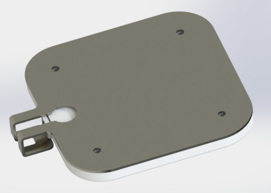
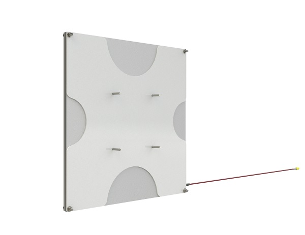
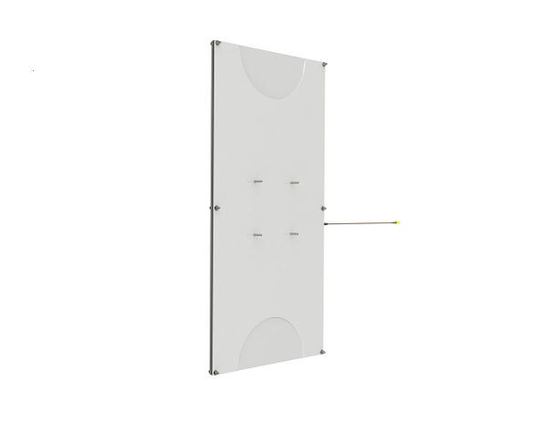
[Fig.1]
The Universal Mounting Plate as shown in Fig. 1 for antenna model A1115 is available with M4 and M6 studs.
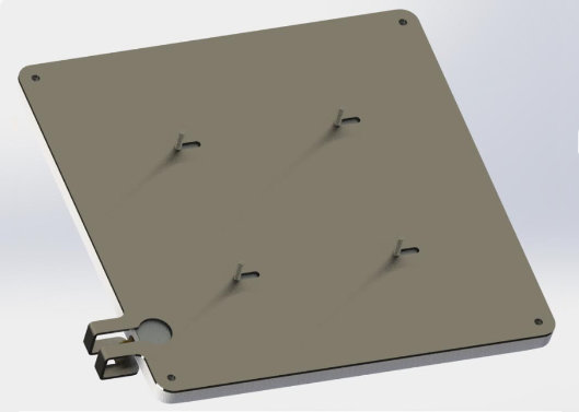
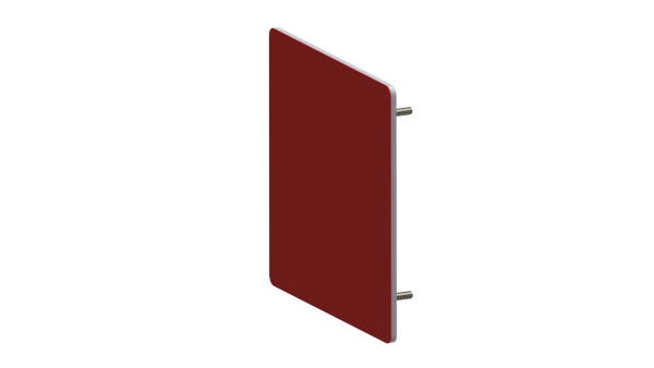
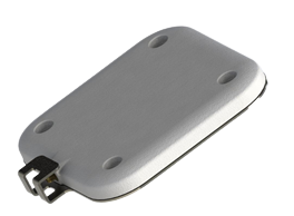
[Fig.2]
Shown in Fig.2 is the Mounting Plate for antenna model A5060. Similar Mounting Plates are available for other antenna models. For more information please refer to the datasheet of the required antenna linked in the table above.
MOUNTING PLATES TECHNICAL SPECIFICATIONS
| Dimensions | Refer to antenna model datasheet |
| Frequency Range | N/A |
| Connector Type | N/A |
| Antenna Gain | N/A |
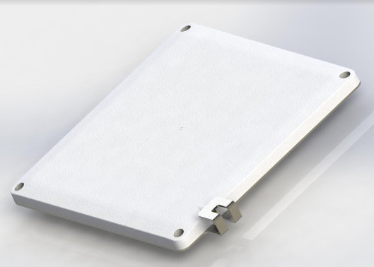
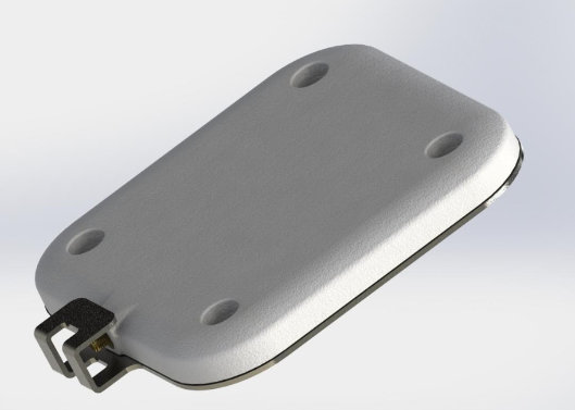
Connector Protection Backplate
Do you want to add more ruggedness and support to your A5020 or A5010 antenna? Some industrial applications require the antenna connector to be protected from hits due to moving machinery in the work environment. To provide extra-ruggedness, we have designed a Connector Protection Backplate.
The Connector Protection Backplate can be flush mounted, or VESA mounted. To install the backplate, attach it to the rear side of the antenna. The backplate bends over the connector, held on via the mounting holes. The backplate can be used with right-angled and straight cables.
For the mechanical drawings of the backplates, please refer to the antenna datasheet linked in the table below.
Order information for the Connector Protector Backplates can be found in the table below.
| Product Code | Part Number |
| A5010 Backplate | 72039 |
| A5020 Backplate | 72394 |